What is active rectifier? simulation of single phase active rectifier In-depth guide to full wave rectifier Bridge rectifier schematic diagram
Bridge Rectifier - Electronics Reference
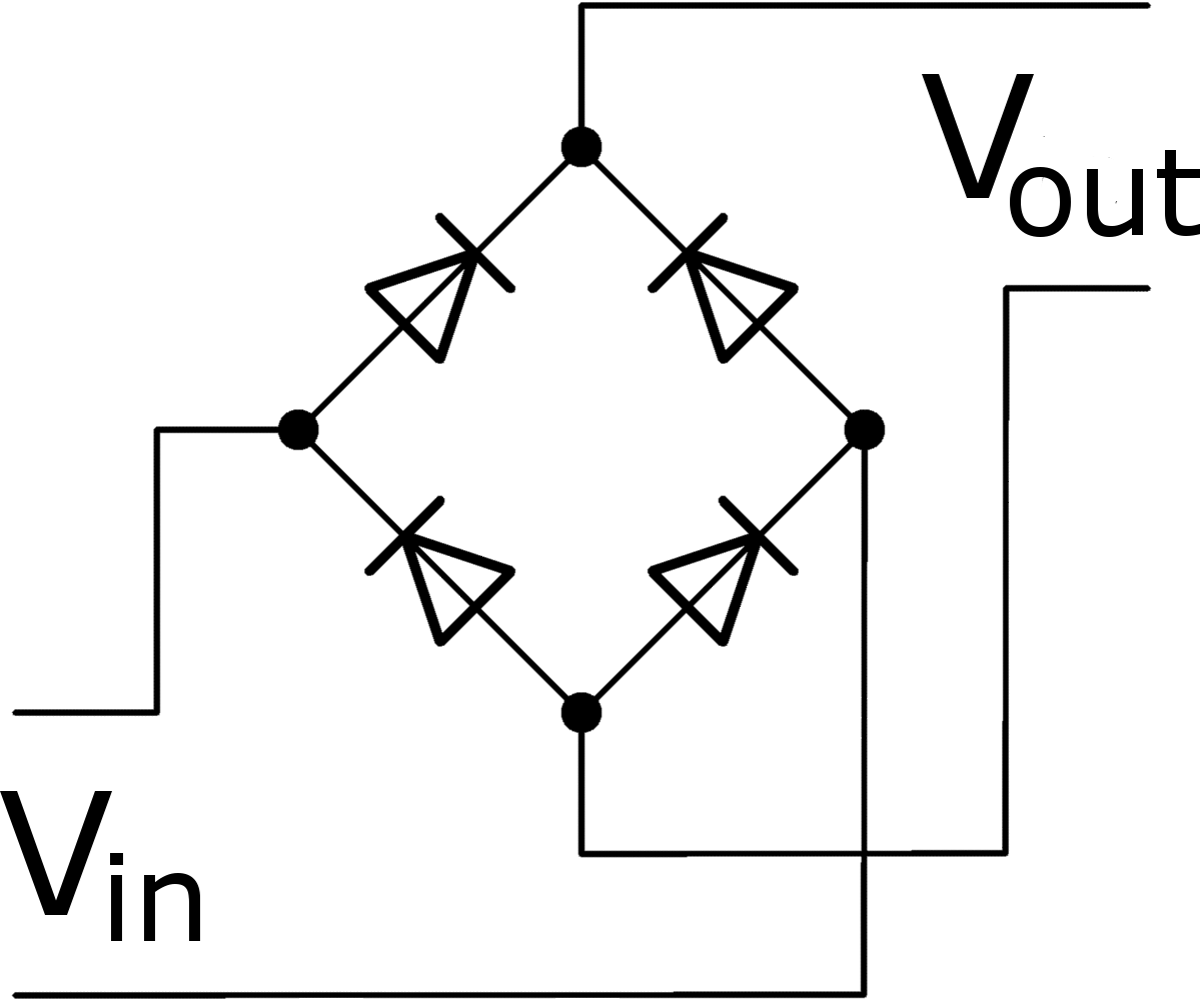
Rectifier schematic
Activity: active rectifiers [analog devices wiki]
Proposed rectifier publicationRectifier precision active op amp circuit opamp diode signal wave half circuits need amplifier using operational voltage inverting svg know Full wave bridge rectifier circuit diagramActive rectifier diagram.
Active_rectifier_schematicActive rectifier circuits: convert alternating current to direct Full-wave active rectifier circuit proposed.Full-wave active rectifier circuit proposed..

Active rectifier wave rectifiers analog wiki activity circuit op powered self half figure
Circuit diagram of the proposed active rectifier.Power supply design notes: rectifier circuits Active rectifierActive rectifier circuits: convert alternating current to direct.
Rectifier diode bridge rectification novices12 volt 4 pin regulator rectifier wiring diagram Si labBlock diagram of rectifier circuit.
(pdf) an integrated power-efficient active rectifier with offset
Full bridge rectifier circuit diagramRectifier active phase single matlab simulation using Schematic of the proposed ds active rectifier [3,10,11].Circuitlab rectifier active circuit description.
Simplified schematic diagram of the active rectifier depicting theWorking of full wave bridge rectifier with capacitor filter pcb designs Bridge rectifierPatent us8284581.

Rectifier power inductively efficient comparators integrated controlled offset
Rectifier diode circuits powerelectronicsnewsRectification explained Bridge rectifier – construction, working, advantagesFull wave rectifier circuit diagram.
Patents active rectifierFull wave controlled rectifier circuit diagram Active rectifier circuits: what you need to know about itIn depth: linear technology's active bridge rectifier.

2: schematic of active and passive rectifier
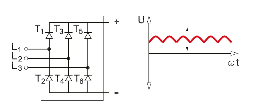
Rectifier circuit filter schematic textbook circuitsProposed active rectifier. Active rectifier amp rectificationPower mosfet three phase rectifier electronic diagram.
.

![Schematic of the proposed DS active rectifier [3,10,11]. | Download](https://i2.wp.com/www.researchgate.net/publication/330318352/figure/fig1/AS:713890732204036@1547216222677/Schematic-of-the-proposed-DS-active-rectifier-3-10-11_Q640.jpg)